How To Wire Up Piezoelectric Sensor A Comprehensive Guide 50 OFF Circuit Diagram
BlogHow To Wire Up Piezoelectric Sensor A Comprehensive Guide 50 OFF Circuit Diagram This is great for an intrusion detection circuit or burglar alarm circuit! Any time the motion sensor senses movement the piezo buzzer will make an audible sound. In this tutorial we will use an active piezo buzzer that does not need a PWM signal to operate. RELATED: Piezo Buzzers: Active vs Passive. Parts List for this Project
In summary, the code continuously reads the analog input from the piezoelectric transducer sensor. When the sensor value surpasses the predefined threshold, it triggers the generation of a tone on the speaker connected to digital pin 8. This can create a sound-producing effect based on the vibrations detected by the piezoelectric sensor.
Piezo Sensor Experimentation : 8 Steps Circuit Diagram
In this project, I will be using the HC-SR04 ultrasonic sensor. You may read more about the HC-SR04 sensor here: Using the HC-SR04 Ultrasonic Sensor to Detect Objects Introducing Piezo Buzzers Piezo buzzers are versatile components commonly used for generating audible alerts and feedback in electronic projects. Hopefully, it's NOT a "buzzer". A buzzer has built-in electronics to generate a sound when you connect it to DC voltage. A speaker/transducer only makes sound when you drive it with an AC signal.: I'm trying to detect a sound with a piezo buzzer, and turn a LED on and off whenever I clap (basically this, except with and LED and Arduino.)

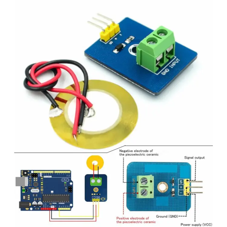
To use a piezoelectric sensor is the easiest task, just connect the positive and negative terminal to your circuit and press the top of sensor. By pressing, due to mechanical pressure it create voltage at output which is further feed to the circuit. Production and detection of sound; Generation of high voltage; Electronic Frequency

Sound Sensor with Arduino Tutorial Circuit Diagram
A typical sound sensor module consists of the following pins: VCC - Power supply (3.3V to 5V); GND - Ground; A0 - Analog output (provides variable voltage based on sound intensity); D0 - Digital output (HIGH or LOW depending on a preset threshold). Specifications. Below is a table with the specifications of a typical sound sensor: Using the Piezo to create small voltages for an LED is an analog way of using it, and using it as a sensor for a microcontroller is a digital way of using it. Here are some analog ways of using it: The Piezo could be used as a small generator for an LED. There is a lot of potential using this technology in children's and babies' toys. Interfacing of Piezoelectric Sensor with Arduino. As we have to know what a piezoelectric sensor is, let's look at Interfacing of piezoelectric sensor with arduino. Here we are trying to operate an LED when the pressure sensor detects enough force. Hardware Required. Arduino board. Piezoelectric pressure sensor. LED; 2 MΩ resistor. Circuit
