Temperature Controlled DC Fan Circuit Diagram
BlogTemperature Controlled DC Fan Circuit Diagram Here the Temperature controlled fan will act to the temperature changes. We have also written a blog on what temperature sensors are, if you are interested feel free to read that as well to understand more about these types of sensors. We are going to do this with a DHT11 temperature and humidity sensor. It can be done in various other ways as
Explanation: The NPN transistor acts as a switch, allowing the Arduino to control the fan. By adjusting the potentiometer, we set the threshold temperature at which the fan will turn on. Step 3: Connect the Potentiometer. Now, let's connect the potentiometer, which will allow us to set the threshold temperature for fan control. Temperature Controlled Fan Circuit Diagram. The complete circuit to build the temperature controlled fan using arduino and lm35 project is given below, we have used fritzing software for making most of the circuit diagrams. The fan and the plug were later added using photoshop. The diagram consists of an arduino,a relay, an lm35 sensor, an AC fan, and a plug.

Temperature Based Fan Speed Controller and Monitoring using Arduino Circuit Diagram
Then we will check if the temperature value is greater than 35 or not, if the temperature will be greater than 35, then the relay will be activated and the fan will start to rotate. Hardware Part First of all, make the connection of the LCD module with the Arduino as follows:

Description: Temperature controlled Fan or Room Cooler using Arduino- In this project, you will learn how to make your own Fan, room cooler, ceiling fan or exhaust fan automatic temperature controller using Arduino, DHT11 temperature and humidity sensor, and a relay module.The Room Cooler or Fan is controlled automatically depending on the room temperature. Temperature-based fan control systems find applications in a multitude of settings, including air-conditioners, ovens, and thermal baths, among others. Our project leverages the precision of the LM35 Temperature Sensor and the versatility of Arduino to create an efficient and responsive fan speed control mechanism. How to Make Temperature Controlled Fan Using Arduino and DHT11: Temperature-controlled fans have become a popular DIY project for keeping your surroundings cool automatically. In this blog, we will guide you through creating a temperature-controlled fan using an Arduino board. With just a few electronic componen…
How to Make Temperature Controlled Fan Using Arduino and DHT11 Circuit Diagram
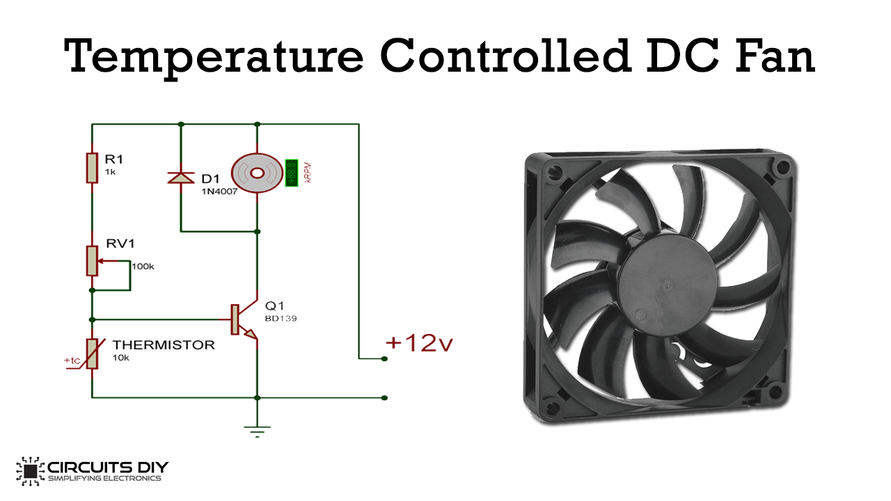
It is rated to operate over a -55°C to 150°C temperature range. It has +10.0mV/Celsius linear-scale factor. The 2N2222 transistor acts as a switch and controls the fan speed depending upon temperature. 1N4007 diode controls the fan from being damaged. The LED glows whenever the temperature exceeds 60°C.
